UTM – Universal Transverse Mercator
UTM Projection
As the name suggests, the Universal Transverse Mercator projection is based on the cylindrical Transverse Mercator projection. The cylinder in the Transverse Mercator projection is tangent along a meridian (line of longitude) or it is secant, in which case it cuts through the earth at two standard meridians.
In the UTM projection the transverse cylinder rotates by 6° increments, thus creating 60 (360° / 6°) strips or projection zones. In such a projection, instead of projecting the complete globe into a flat surface, each of the 60 strips or zones gets projected onto a plane separately, therefore minimizing scale distortion within each zone. The meridian at the center of each zone is called the central meridian. The cylinder is secant in the UTM projection; it intersects the globe creating two standard meridians that are 180 km to each side of the central meridian. Also since a Transverse Mercator projection results in extreme distortion in polar areas, the UTM zones are limited to 80°S and 84°N latitudes. Polar regions (below 80°S and above 84°N) use the UPS - Universal Polar Stereographic coordinate system based on the Polar Stereographic projection.
The narrow width (6° of longitude) of each zone ensures minimal scale distortion within a zone. Also a map derived from a secant cylinder has less overall distortion than a map from a tangent cylinder. The scale is true (scale factor = 1) on each of the standard meridians meaning that there is no distortion along these lines. Between the secant lines, where the cylinder is inside the globe, features appear smaller than in reality and scale factor is less than 1. The central meridian has a scale factor of 0.9996. At places on map where the cylinder is outside the globe, features appear larger than in reality and scale factor is greater than 1. The scale error within each UTM projection zone remains less than 0.1 percent, or in other words scale distortion is kept to less than 1 part in 1000. Naturally for areas that span more than one UTM zone, the distortion and error increase.
The Mercator and Transverse Mercator projections are conformal projections. In a conformal projection local angles are preserved and shapes are represented accurately and without distortion for small areas. As a result of preserving angles and shapes, area or size of features are distorted in these maps. As mentioned, choosing a secant projection and a narrow zone minimizes the distortions in a map generated from UTM projection.

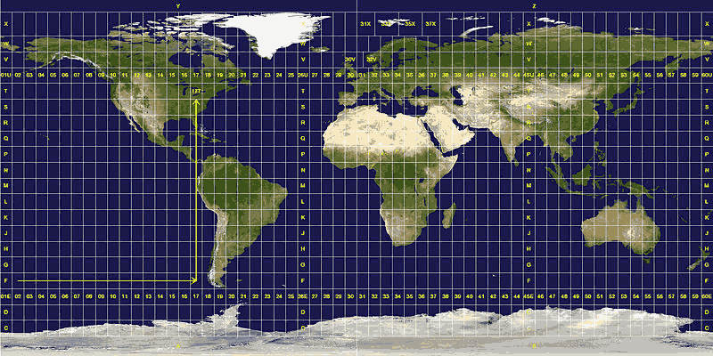
UTM grid zones on a projected map of the world © Wikimedia Commons
UTM Zone
UTM zones are numbered from 1 to 60 starting from 180° longitude at the International Date Line and proceeding eastward. Each zone is 6° longitude wide. Therefore Zone 1 lies between 180°W to 174°W longitude lines, Zone 2 is between 174°W and 168°W longitude lines, and Zone 60 lies between 174°E and 180° (International Date Line) longitude lines.

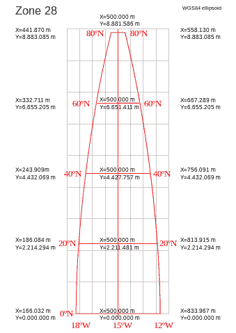
UTM Zone – northern hemisphere © Wikimedia Commons
Each zone is divided into horizontal bands 8° of latitude wide. The 20 bands are labeled with letters, beginning with C and ending with X from south to north. Letters I and O are omitted to prevent confusion with numbers one and zero. Note that letter N designates the first latitude band above the equator, so any letter of alphabet after N refers to a band in northern hemisphere and any letter before N refers to a band in southern hemisphere. Letters A, B, Y and Z label polar regions in the UPS coordinate system. To specify a UTM grid zone, the zone number (column) is given before the zone letter (row), such as Zone 11U.
Each zone has a central meridian which extends north–south along the middle of the zone (3° from the east and west zone boundaries), splitting the zone into two equal halves. For example, as shown in the figure, zone 28 (northern hemisphere shown) is bounded by 18°W meridian to the left and 12°W meridian to the right. The central meridian of the zone lies along 15°W meridian or line of longitude. Since UTM zones are bounded by lines of longitude and these lines converge towards the poles, consequently the width of each zone tapers (narrows) from the equator towards the poles.
Zone divisions with horizontal bands, as above, result in each division having dimensions of 6° longitude wide and 8° latitude high. However, there are exemptions, where dimensions of some zones are adjusted. The northernmost band (X) is 12° latitude high instead of 8° and extends from 72°N to 84°N latitudes. Zone 32V covering west coast of Norway is widened to 9° longitude instead of 6°, resulting in narrowing of Zone 31V. Zones 33X and 35X have been widened to 12° to cover Svalbard. Similarly zones 31X and 37X are widened to 9°. As a result zones 32X, 34X and 36X have been omitted.
UTM Coordinate System – UTM Grid
By means of a map projection, the earth's curved surface is transformed to a flat two–dimensional surface. A coordinate system or grid is superimposed on the resulting flat surface. Such a coordinate system provides a referencing frame in order to define the position of objects.
Universal Transverse Mercator is a projected coordinate system, which is a type of plane rectangular coordinate system (also called Cartesian coordinate system). In the two–dimensional surface, two straight lines intersect each other at right angles. These lines are called the axes, and their point of intersection is defined as the origin (0, 0) of the coordinate system. The horizontal axis (east–west) is labeled as x–axis and the vertical axis (north–south) as y–axis. The position of a point in the rectangular coordinate system is defined by its distance from the x and y axes. The two distance values are the x and y coordinates of the point, and use a measurement unit such as meters, feet, etc.
The intersection of the x and y axes in the rectangular coordinate system divides the space into four quadrants. Points along a vertical grid line to the right of y–axis have a positive x coordinate value while those to the left of y–axis have a negative x coordinate value. Points on a horizontal line above the x–axis have positive y coordinate value while those below x–axis are given negative y value. Therefore a point lying in the first quadrant, to the right of y–axis and above x–axis, has positive x and y coordinate values.
In contrast to the projected coordinate system, the geographic coordinate system uses curved grids in order to accommodate the curved surface of the earth; and the geographic latitude, longitude coordinates are measured in degrees, minutes and seconds of arc. These geographic coordinates are converted to plane coordinates by means of map projections.
The UTM coordinate system is a universally used plane coordinate system (except for polar regions). UTM zones are "flattened" using the Transverse Mercator projection, and a rectangular grid network of straight horizontal and vertical lines is superimposed on each zone. Although meridians inside the zone and on zone boundaries converge towards the poles, vertical grid lines are oriented parallel to the central meridian of each zone (and make an angle to the other meridians). Horizontal lines in turn are parallel to the equator. As a result the grid squares stay the same size and shape throughout the map.
The vertical direction of grid lines is referred to as grid north on maps, as opposed to true north which is associated with the direction of meridians or lines of longitude. The angular difference between grid north and true north is referred to as grid declination, and is sometimes indicated on the map margin along with magnetic declination. For large scale maps this difference is small and is usually not taken into account in map reading.
In the UTM grid layout, the unit of measurement is meters, and the coordinates of a point are designated as easting (determine east–west position) and northing (determine north–south position). Vertical grid lines on map are used to find easting while horizontal grid lines are used to find northing of a point; similarly grid lines can be used to help locate a point with known coordinates.
Designation of the central meridian as the reference y–axis (i.e. easting = 0) of the coordinate system within each zone would result in negative easting values for points to the west of the central meridian. For this reason, the central meridian is assigned an arbitrary value of 500000 meters, thus avoiding any negative easting coordinates; points lying to the east of it would have an easting value greater than 500000m and points lying to the west would have a value less than 500000m. This assignment would place the origin outside the zone at 500000m west of the central meridian, as a result the origin is called a false origin and the easting coordinates are referred to as false easting.
The equator is designated as the horizontal reference axis for UTM northing coordinates and is assigned a value of 0 meters North for zones in northern hemisphere. To avoid negative numbers, the equator is assigned a false northing of 10,000,000 meters South for referencing northing coordinates in the southern hemisphere.
UTM Coordinates – Easting, Northing
Easting
The easting coordinate of a point is measured from the false origin 500000 meters to the west of the central meridian of the UTM zone. Within a zone, easting values increase towards east. A point lying 8 meters east of central meridian has an easting of 500000 + 8 = 500008mE. The easting of a point 350m west of central meridian would be 500000 – 350 = 499650mE. The east–west distance between two points is obtained by the difference of their easting values. The distance between the above points is 500008 – 499650 = 358m.
Longitude lines are furthest apart at the equator, where latitude is zero. Therefore the maximum width of a UTM zone occurs on the equator. Depending on the datum and the chosen ellipsoid, an approximate range for the easting values can be calculated. In general the easting values can not be larger than 834000m and smaller than 166000m. As a result, an easting coordinate is always a six digit number. Sometimes in GPS systems and GIS software, the easting values are preceded with a 0 in order to represent them as 7 digit numbers.
Northing
A northing value in northern hemisphere specifies the number of meters a point is located north of the equator. The northing of a point south of the equator is equal to 10,000,000m minus its distance from the equator. In both northern and southern hemispheres, northing values increase from south to north.
A point south of equator with a northing of 7587834mN is 10,000,000 – 7587834 = 2412166m south of the equator. A point located 34m south of the equator has a northing of 9999966mN, while a point 34m north of the equator has a northing of 0000034mN. The north–south distance between two points north of equator with northings of 4867834mN and 4812382mN is 4867834 – 4812382 = 55452m.
Depending on the datum and the chosen ellipsoid, an approximate range for the northing values can be calculated. In the southern hemisphere the northing values range from 10,000,000m at the equator to approximately 1100000m at the 80th south parallel. In the northern hemisphere the northing values stretch from 0m at the equator to around 9350000m at the 84th north parallel. If the northing values are less than 7 digits, they will usually be preceded with 0(s) to represent them as 7 digit numbers.
UTM easting and northing coordinates specify the position of a point on Earth. UTM coordinate of a point is stated by writing the zone, easting and then northing values. When finding a position on a map, it is helpful to "read right up", that is to read west to east to find the easting and then south to north to find the northing of the location. An example of a complete UTM coordinate: 11U 358657mE 5885532mN.
Since there are coordinate values that occur in both northern and southern hemispheres within a UTM zone, it is important to specify the hemisphere or the latitude band where the point is located. Usually GPS receivers can use both ways to distinguish the hemisphere. Care should be taken so that stating the hemisphere by the use of N (north) or S (south) after the zone number not to be confused with interpretation of N or S as latitude band letters.
UTM Abbreviation
Outdoors guide books sometimes specify UTM coordinates in an abbreviated format when referring to a particular map of an area. An abbreviated or truncated UTM grid reference (GR) is stated as an even number with 4, 6 or 8 digits. The first half of the number refers to the easting and the second half to the northing coordinate of a location.
Since each easting or northing coordinate is a base 10 number, the right–most digit is the ones meter place; moving left next digit is the 10s meter place, third digit from left is the 100s meter digit and so on. A complete UTM coordinate including all the digits, such as 12S 565234mE 4325782mN, specifies the location of a point within a 1m by 1m square. When abbreviating a UTM coordinate, the 100,000s digit (sixth digit from right) and the 1000,000s digit (seventh digit from right) are omitted. Then depending on the desired accuracy, the 100s, 10s, or ones digit is added to each easting and northing coordinate. It is possible to define a location within 1000m, 100m, or 1m. Keep in mind that no rounding of numbers takes place during truncation.
To abbreviate 12S 565234mE 4325782mN coordinate, the left–most 5 (100,000s digit) from easting is omitted along with left–most 4 and 3 from northing (100,000s and 1000,000s digit). The grid reference can then be stated as: GR 6525 defining a 1000m x 1000m square (accurate to within 1000m); GR 652257 defining a 100m x 100m square; or GR 65232578 defining a 10m x 10m square. A 10 digit grid reference defines a 1m x 1 m square similar to the complete UTM coordinate: GR 6523425782. The six digit and eight digit grid reference formats are used more commonly.
Latitude Longitude vs. UTM – Zone Boundary Problem
There are some advantages in using UTM coordinate system in comparison to latitude and longitude coordinates. In the UTM coordinate system, grid squares are the same size and shape throughout the map. In contrast, in the geographic coordinate system the distance represented by one degree (or minute or second) of longitude varies with latitude, therefore the units of measure do not remain constant across the globe. The distances measured in degrees or minutes of longitude can not be compared at different latitudes.
In UTM all measurements are done in meters. Coordinates are always positive and there is no need for N, E, W, S designations. There are no conversion between formats, such as between decimal and DMS. Coordinate values of a point identify its position within the familiar Cartesian coordinate system. Coordinates within a zone can be directly added to each other and subtracted from each other. Therefore calculation of distances, directions and areas can be performed much more conveniently in comparison to geographic coordinate system.
The narrow width (6° of longitude) of each zone and the use of a secant developable surface for projection ensures minimal scale distortion within a zone. UTM is not suitable for areas that span more than a few zones since distortion and error increases when moving farther from the zone for which the projection is defined. When working across zone boundaries multiple coordinate systems must be used. Coordinates in adjacent zones do not have a mathematical relationship.
Large scale maps usually include the coordinates of the adjacent zones (each zone is extended into its neighbor) when a zone boundary falls within the map, that is more than one zone or portion of are shown on the map. When a feature or desired locations fall into two zones, coordinates can be measured and stored consistently by using the same grid system.
Some other methods to address the zone boundary problem in UTM include: using a different zone width for the desired areas (e.g. 3° Modified Transverse Mercator – MTM in Canada); setting a different value for central meridian so that one zone would cover the area of interest; in GIS, reproject data from one zone to the projection of the neighboring zone that contains larger portion of the area; reproject both zones into a different projection; convert data to latitude, longitude geographic coordinate system. The last three methods allow for merging of data, analysis and storage within the GIS database.
UTM and Datum
A coordinate system may be based on different datums. Different maps may refer to different datums, or the datum referenced by the GPS receiver may not correspond to the one for the map. For example older maps in North America are based on NAD 27 datum while recent maps are based on NAD 83. The default datum for GPS receivers is usually initially set to World Geodetic System of 1984 (WGS 84). And interactive maps such as Google Maps and Bing Maps use the WGS 84 datum.

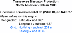
Example of map datum and coordinate conversion
Transferring coordinates between map versions, GPS and map or digital and paper maps might cause errors in location of coordinates due to the mismatch of datums. For example transferring coordinates of a trail junction from a map based on NAD 27 datum to a GPS that is set to WGS 84 datum may result in the GPS showing the location of the trail junction couple hundred meters off from the actual location.
It is important to state the datum when working with geographic data. Guidebooks usually specify the datum for the coordinates they provide. The datum in GPS receivers can be set to correspond to the desired map's datum. The datum is printed on the margin of topographic maps, sometimes along with information for conversion of coordinates between two different datums by addition to or subtraction from northing and easting values; such as the example to the right.
Example of change in datum between map versions: http://www.nrcan.gc.ca/earth-sciences/geography-boundary/mapping/topographic-mapping/10129.
UTM on Map – Grid Reference
UTM gridlines are usually shown on the map, or ticks are marked on the margins of the map. The tick marks can be connected by the use of a straight edge to produce gridlines. Depending on the scale of the map, the distance between grid lines may differ. For example on US Geological Survey (USGS) 7.5–minute quadrangle maps (1:24000 and 1:25000 scale) and 15–minute quadrangle maps (1:50000, 1:62500, and standard–edition 1:63360 scales) as well as Canadian NTS 1:50000 maps gridlines are 1000m (1 km) apart. On the other hand smaller scale Canadian NTS 1:250000 and USGS 1:100000 and 1:250000 scale maps show gridlines at 10000m (10 km) intervals. The grid interval is usually indicated on the map margin. The ground distance of the grid interval can also be measured by the use of the map scale.
Gridlines or ticks near the corners of the map are designated with full coordinate values. Abbreviated values, called principal digits (two larger numbers), are usually used to label the other grid lines. To find the UTM coordinate of a point, "read right up". The numbers designating the vertical gridlines (at the bottom or the top of map) are the easting values. The numbers to the sides of the map labeling horizontal lines are the northing values.
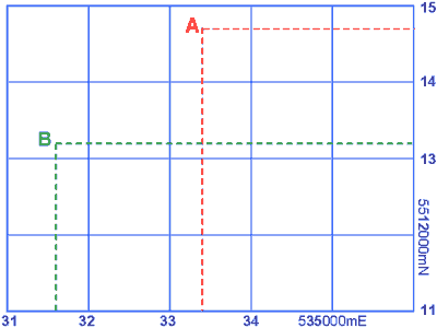
In the map example below, grid lines are 1000m apart. That is each grid square is 1000m x1000m. To find the easting of point A, value of the nearest grid line to the left (west) of the point is found. In this case the grid value is 33 or 533000mE. The eastward distance of point A to the grid line is added to this grid line value. The distance of point A can be estimated, measured by using the map scale, or measured with a ruler as done in latitude, longitude map example. Estimating in tenths of a square would locate point A around 0.4 of the length of square to the east of gridline 33. In meters this distance would be 0.4 x 1000m = 400m. Therefore easting of point A is 533000 + 400 = 533400mE, or in abbreviated format 334.

Example of UTM grid on map
To find the northing of point A, value of the nearest grid line below (to the south) of point A is found. Here the grid line value is 14 or 5514000mN. The northward distance of point A to the grid line is added to this grid line value. Estimating in tenths of a square would locate point A around 0.7 of the length of square to the north of gridline 14. In meters this distance would be 0.7 x 1000m = 700m. Therefore the northing of point A is 5514000 + 700 = 5514700mN, or in abbreviated format 147. The complete UTM coordinate of point A which is in grid zone 10U is: Zone 10U 533400mE 5514700mN. The abbreviated grid reference is: GR 334147. This coordinate defines location of point A to within 100m. Keep in mind that when communicating coordinate values in an abbreviated format, the map of the area or map sheet number should be specified (e.g. 92 G/15).
If the UTM coordinate of a point is known, it can be located on the map by pinpointing its easting and northing similar to the above. Sometimes in guidebooks UTM coordinates are provided in an abbreviated format. These suffice to find locations on the map. However for inputting coordinates in a GPS receiver, complete easting and northing coordinates are needed.
In this example, grid reference of point B is GR 316132. From this grid reference, the easting abbreviation is 316 and the northing is 132. A six digit grid reference defines a 100m x 100m square. From the map it is evident that the easting should be between 31 (531000) and 32 (532000) eastings. The 100000s digit of the easting is 5; also 6 in 316 abbreviation is the 100s digit. Since the accuracy is to within 100m and the 10s and ones digit are not defined, they can be represented by 0s, which results in a complete easting of: 531600mE. Similarly northing 132 is located between 13 (5513000) and 14 (5514000) grids. Placing 0s for the tens and ones digit would provide the complete northing: 5513200mN. The UTM coordinate is: Zone 10U 531600mE 5513200mN.
If the abbreviated grid reference is given in 8 digits, finding the complete coordinate is similar to the above. For example for GR 31671324 the easting component is 3167 and the northing component is 1324. The eight digit grid reference defines a 10m x 10m square. Here the 10s digit is provided, and 0 can be placed for the ones digit. The complete UTM coordinate is: Zone 10U 531670mE 5513240mN.
For a more accurate way of reading or plotting UTM coordinates on maps some tools such as UTM corner ruler or roamer, grid overlay tool, and slot card can be used. Keep in mind that the tool should match the scale and the grid size of the map you are working with.